
Preview / Read the Current Issue of SSS
Volume 5 - Number 1 -- Spring 1997
Updated 8/6/97
[SIRIUS COMMUNICATIONS CDMA
MODEM DEVELOPMENT KIT]

Part 2

New Products

SIRIUS COMMUNICATIONS CDMA
MODEM DEVELOPMENT KIT
The Development Kit is an extension to the
Sirius Communications PMCM Development Board

It allows to continuously monitor in real-time
up to 6 simultaneous receiver signals, such as correlation
values, the receiver phase error, the AGC value, the carrier
recovery and the timing recovery. A complex constellation diagram
can also be shown. These measurements allow to quickly evaluate
the performance of a receiver, and to tune the transmitter and/or
receiver parameters. The PMCM Development Board allows to program
a huge range of modem parameters, and to derive Bit Error Rate
(BER) figures. The effect of typical parameters of the
Development Board can immediately be quantified using the PMCM
Development Kit. For instance, the step response of the PLL for
carrier recovery can be visualised as a function of the PLL gain
and PLL bandwidth.
The PMCM Development Kit consists of 3
parts:
1. Development Kit Monitor software
The Development Kit Monitor software can
simultaneously handle 6 measurements out of a set of 32 receiver
signals. This set can be freely assigned by the user, and the
configuration can be done from the Development Board terminal
window. Any of the 6 measurement channels can be plotted on a
time axis, or in a complex plane, or both at the same time. The
following 2 examples the system under test uses QPSK with
different codes of length 15 on the I and the Q branches. This is
also called QPN (Quadriphase Pseudo-Noise).
At the left of the screen, the 2 upper function
plots show snapshots of the correlation data of I and Q channels
with each code, as a function of time. The third functional plot
shows the chip frequency offset at the receiver (D_RX_FCHIP) and
the frequency offset (D_RX_CARR) of the receiver carrier, as a
function of time.
At the right of the screen, the constellation
plot of the demodulated QPN signal is shown.
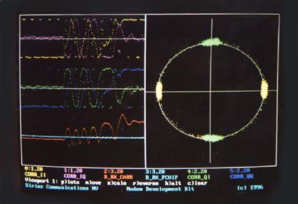
Lock-in behaviour of carrier
tracking PLL
As a result of a carrier frequency step at the
transmitter side, the receiver carrier frequency starts to
produce a beatnote, that slows down in frequency until lock is
reached. During pull-in, correlation values are unusable, and
become stable again when lock is reached. The receiver chip
frequency offset (D_RX_CARR) remains unaffected. The transient
behaviour results in constallation dots outside the main spots.
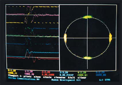
Receiver response to step in
transmit chip frequency.
As a result of a chip frequency step at the
transmitter side, the receiver chip frequency (D_RX_FCHIP) offset
starts evolving towards a new stable value. The receiver carrier
tracking loop (see D_RX_CARR) goes through a transient behaviour,
due to the coupling with the chip frequency tracking loop, and
then reaches again its original value.
2. PMCM software extension
The PMCM software running on the TMS320C31 is
extented with a separate monitor process, that runs on the
frequency of one of the internal timers of the TMS. This monitor
process selects 6 out of 32 measurements and sends them to the PC
via the ISA board.This set of 32 monitor signals is updated by
the PMCM receiver process every symbol.
To match the slower speed of the PC, the
selected measurements are automatically downsampled by the
monitor process. However, independent of the speed of the PC
running the Development Kit Software, the measurement set is
always kept consistent. The faster the PC, the higher the
resolution of the measurements plotted on the screen of the PC.
The TMS monitor process is provided as source
code, and is open to the developer, who can add his own signals
to observe via the Development Kit, up to a maximum of 32
signals.
3. ISA interface board
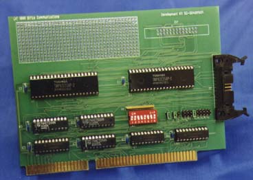
The PMCM Development Board
communicates to the PC via an ISA interface board. The 16-bit ISA
Board provides a 16-bit handshaked output for the Development Kit
software. It can also be used as a 16-bit parallel input/output
port to the PMCM Development Board.
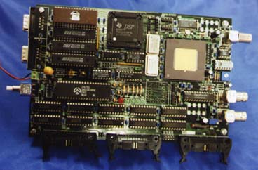
This CDMA/Spread Spectrum Development Board
(second generation) provides a configuration with the PMCM IC and
the TMS 320-C31 DSP. This allows full flexibility in modulation
schemes, data rates, spreading codes, tracking loops,
synchronization algorithms, acquisition strategy, etc.
FEATURES
- Stand-Alone operation or
interfacing with terminal
- Serial PC interface
- Programmable IF in both
transmitter and receiver
- Programmable sample rate in
transmitter and receiver
- Programmable symbol rate
- Custom spreading codes and code
lengths
- Various modulation schemes
- Correlation data dump for
visualization of constellation plots
- Flexible tracking, demodulation
and data formatting
- Performance measurements such as
real-time BER calculation
- Comprehensive tutorial included
|
To ask for the data sheets, contact Kristoffel
Mulier at:
Sirius Communications NV
Wingepark 51
B-3110 Rotselaar
Belgium
tel: +32 16 44 44 02
fax: + 32 16 44 54 81
Please Contact
us today!
In October 2000, this website and the copyright to all editions of
Spread Spectrum Scene Online was purchased by
SSS Online, Inc., and is operated by
Pegasus Technologies. For more of the best information
on RF, Spread Spectrum and wireless, press one of the buttons below:

|
|
|