From the RF/SS Workbench
This new column should be of interest to many of our readers. In it I plan to share
experiences with components, tools, design techniques and projects that we have been
involved with Hopefully, we will also share handy, helpful hints and tidbits and
trivia that may benefit others in this field.
In one of our latest projects we have made use of the Stanford Telecom SREL -2000A-45
IC DS "Modem." This versatile chip can do many things in many different
applications. It was designed for burst mode communications and as such has separately
programmable preamble and data spreading codes. It is capable of half or full duplex DS
communications. It offers a host of features and options -- this makes it rather
complicated to use! See the sidebar on this page for more information about this chip.
We have called this chip the result of a "PhD dissertation" -- because you need
almost a PhD to understand how the chip works and to be able to program its many registers.
This chip is not designed for the faint of heart or casual SS system designer. Excellent
results can be had using this chip, however. Evidence the 5 MChip/sec QPSK spectrum plot
shown on the front cover. This spectrum was captured on our Wandel & Galtermann TSA-1
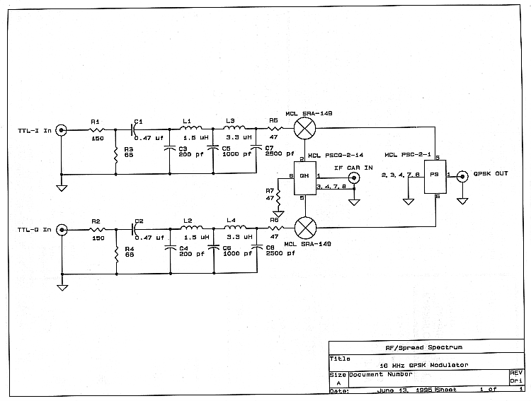
Tracking Generator / Spectrum Analyzer. The QPSK modulator design is shown schematically on
page 9. The 16 MHz center frequency output of this modulator provides an example of what
can be done with pre-modulation filtering in a DS QPSK modulator. The STEL chip was
programmed for an 11 bit long Barker "PN" code (same code for data and preamble)
which gave a baseband data rate of 909.09 kBps. The DS QPSK symbol rate was 5 Mbits per
second for these tests. Thus a processing gain of 10.41 dB was achieved with this waveform.
Note that the output spectrum is 10 MHz wide, fist null first null and approximately 8 MHz
wide at the -20 dB bandwidth. The 3 dB bandwidth of this signal is approximately 4 Mhz. Note
that the first sidelobe peaks are approximately -40 dBc from the peak of the signal.
Many of you may think that a QPSK signal filtered this much may produce a lot of Bit
Errors or produce an unacceptably high implementation loss. However, in our tests
with a coherent QPSK demodulator (to be described in our next issue) we found the
implementation losses of this amount of filtering when used with a companion STEL-2000A-45
IC to be less than 3 dB! Better results could certainly be attained with FIR digital
pre-modulation filtering or using non-linear filtering a la FQPSK. For more information
on FQPSK, see the June 1995 issue of RF Design magazine, pages 26-34, "DSP
Implementation of GFSK, GMSK and FQSK Modulated Wireless Systems. "But for a
simple, "quick and dirty" QPSK Modem, this scheme provides very acceptable
performance with near minimum RF bandwidth. In fact, this overall modulation and
filtering scheme achieves an RF to data rate bandwidth ratio of just 1.6 -- considering
the -20 dB (or 99%) bandwidth.
16 MHz QPSK Modulator Schematic [click on image for larger picture]
The RF (or IF) components of the modulator follow a very straightforward design.
Individual I and Q 5th order Bessel passive low pass filters (with 2.75 MHz cutoff
frequency for BT=.55) drive standard Mini-Circuits discrete DBMs, Quadrature Hybrids
and Power Combiners. The tight low pass filter bandwidth (low BT product) of the
pre-modulation filters does cause some transmitted signal distortion, but this
filtering is responsible for the nice output spectrum shown on the cover spectrum
plot. The Bessel filter response was chosen over Butterworth to better approximate
flat group delay in the filters passband. Remember that no IF bandpass filtering was
used with this modulator. MiniCircuits and several other vendors offer packaged
QPSK modulators in a single device -- but beware, some of these designs will not achieve
the RF bandwidth or flatness that this discrete design is capable of . After all, this
design provides a spectrum, at -60 dBc, of 16 Mhz bandwidth (equal to center frequency
or 100% bandwidth)
When IF loopback tests were done with this modulator looped back to the outboard QPSK
demodulator, both transmitted and received I and Q eye patterns showed approximately
10% Intersymbol Interference (ISI). This level of ISI causes some bit errors at low
Eb/No ratios and the differential encoding used with the STEL causes additional double
bit errors. Thus, this design is certainly not an "optimum" modulator or
demodulator in any sense. This modulator is an easily duplicated design, provided you
can program and control the STEL chip correctly. Future columns here will go into these
"details."
Next month we will cover a discrete coherent QPSK demodulator that was used in
conjunction with this modulator for bench tests. This demod was developed
specifically to look at received analog I and Q eye patterns that are not
available from the STEL chip demodulator. Hopefully this series of articles
will give the reader some ideas for further experimentation with DS QPSK.
In future columns we plan to examine various IF and RF MMICs as well as other
ICs that have proved very useful here at RF/SS. We will also pass along tips
on inexpensive antennas for 915 and 2450 MHz, application circuit tricks and
other items of general interest.

Return to Table of Contents for this issue
In October 2000, this website and the copyright to all editions of
Spread Spectrum Scene Online was purchased by
SSS Online, Inc., and is operated by
Pegasus Technologies. For more of the best information
on RF, Spread Spectrum and wireless, press one of the buttons below:

|
|
|