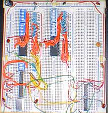
A picture of this PN Generator built on a digital breadboard with
an internal power supply. The unit shown actually has two of these universal PN generators on it,
for experimenting with PN code correlation characteristics.
no programming, no EPROM blowing
and no PAL /GAL is required! Just set the desired bit stream length in dip
switch S1 and enter the desired "code" into dip switches S2 and S3, one bit
at a time. If you enter a PN code into the dip switches, you get the desired PN code at
the output. Entering any arbitrary stream up to 16 bits long will also generate an output,
even though it may not be a "real" PN code, since there are no "smarts"
provided in this design!
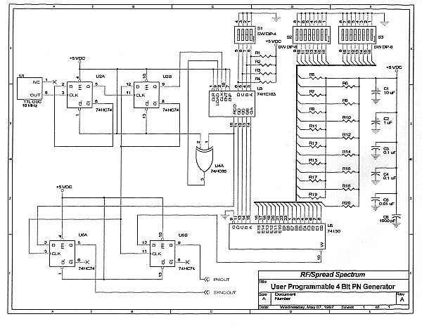
This simple design is based on the old TTL 16 bit multiplexer, the 74150. This part is
still available in a few places like Jameco and JDR, so you should be able to find them.
The virtue of using this part is that ANY up to 16 bit pattern can be entered via S2
and S3 -- thus generating ARBITRARY 1 to 16 bit patterns for a variety of tests / experiments
with PN codes or other digital sequences. We used a 10 MHz TTL 14 pin Dip clock in our
prototype; any clock up to about 20 MHz should work here, however. Go too fast though,
and the 74150 will not keep up!
By the way, the 20 resistor pull ups shown in the schematic below are not at all critical --
use any value between 3.3K and 10K -- but, try to make them all the same value! As
shown in the schematic, each IC should have at least one Vcc bypass capacitor of its own.
I used six capacitors total -- more are better! Other details of this circuit are not at
all critical, especially at the speeds shown here!
U2 is used to divide the frequency of the clock down to 2.5 MHz (or 1/4 of whatever clock
you use.) This was done for several reasons, some of which will be explained later.
One reason for dividing the clock down by 4:1 is to keep the PN clock rate low enough so
that low cost, low speed scopes and other test equipment can be used with this design.
The 2.5 MHz PN clock gives us a PN "chip rate" of 2.5 MHz or 2.5 MChips per second. The
counted down by 4:1 clock drives the 74HC163 - 1 to 16 bit programmable counter.
Note that this counter's length controls the length of the PN stream generated by this
design. Just enter the twos-complement of the code length you want on S1 to set the desired
sequence length. Note that no master reset is provided on this design -- so you may need to
power the circuit down and up again to ensure changed settings on the dip switches are
properly timed and input to the circuit.
The schematic of this simple design is shown below. You may download the schematic in
either ORCAD CAPTURE .DSN or standard .DXF format by clicking on the appropriate line
below the online gif schematic.
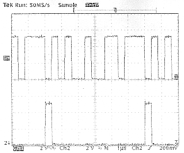
A TEK TDS350 Scope picture of the output of this PN Generator.
The top trace is the PN stream, the bottom trace is the sync signal (or PN Epoch).
This pic was taken with the scope's Bandwidth limited to 20 MHz.
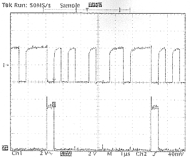
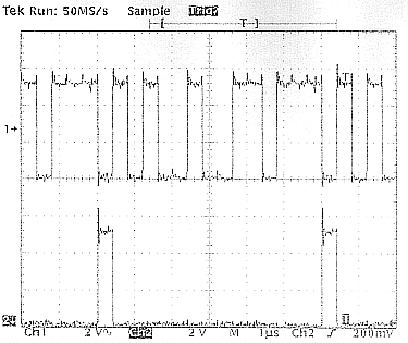
A TEK TDS350 Scope picture of the output of this PN Generator without
using U6 to re-time and cleanup PN and Sync.The top trace is the
U5-pin 10 signal direct, the bottom trace is the U3-pin 15 signal direct.
Note that both traces are noisy and have a few glitches with this setup.
U6 was added to give the "cleanest" PN and sync signals possible --
yet retaining the correct timing between PN and Sync (Epoch).
This pic was taken with the scope's Bandwidth not limited.
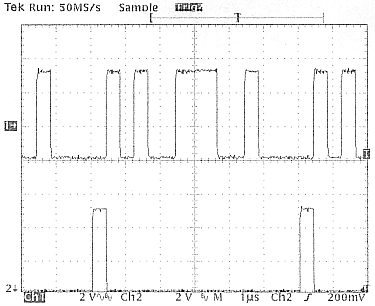
A TEK TDS350 Scope picture of the final output of this PN Generator.
The top trace is the PN stream, the bottom trace is the sync signal (or PN Epoch).
This pic was taken with the scope's Bandwidth not limited.
Note that whatever noise or glitches that are present,
are ONLY digital sampling scope "artifacts."
The PN code set into the dip switches here is: 010100100110111 -- a 15 bit
pattern also known as: 2937HEX. Switch S1 was set for a 1 on its LSB, thus
giving a 15 bit long bit stream. Let's try another bit stream: 29B8HEX
(or 010100111001000 in binary) -- a Maximal Length Sequence from a 4 bit shift
register type PN generator. This pattern is shown below:
A TEK TDS350 Scope picture of the output of this PN Generator with
a 15 bit Maximal Linear Sequence output. The top trace is the
PN stream, the bottom trace is the sync signal (or PN Epoch).
This pic was taken with the scope's Bandwidth limited to 20 MHz.
This circuit design was specifically put together to be able to build up two
(nearly identical) 1 to 16 bit PN generators on the same prototype board to
enable demonstrations, experiments and tests of correlation, cross-correlation
and synchronization techniques. I hope to put together a "PN Training Kit"
using this approach that is not only inexpensive, but modular and expandable.
This kit will include the ability to change the divide by 4. in the second 1 to
16 bit PN generator, to allow a divide by 3 / 4 / 5 "Incremental Phase Modulator"
to be implemented for receive PN synch purposes (now you see why we divided the clock
by four in our "basic" design). We'll also provide a VCXO for the second TTL crystal
clock. I plan to add both early-late and "Tau Dither" tracking circuitry for baseband
PN tracking loop demonstrations. Stay tuned as this kit develops -- perhaps you
have some other ideas about what might be included in this "PN Trainer?" PLEASE
CONTACT US, IF YOU DO!
Questions, comments or suggestions on
anything covered in this column are
welcome. Please feel free to share any
info or special knowledge you may have. Just drop us an email: