SSS Online is proud to highlight selected ICs for Wireless, Spread Spectrum and Digital
Communications. We at Pegasus Technologies make our living developing new products and
need to have an intimate working knowledge of the very latest chips. We are glad to share some
of our chip "secrets" with you on this page, although we don't always have time to keep
it up to date — new chips come on the market a lot more frequently than our engineers get around
to writing about them! If you need any help designing circuits,
systems or equipment / instrumentation around any of these chips or others not mentioned here, please call us at
TEL: 865-717-9339, FAX: 865-717-9904 or email: .
by Eric Myers, Senior RF Circuit Design Engineer, Pegasus
Technologies, Inc.
Editor's note: This is both a chip review and the lead-in for a related article on Layout Considerations for the TI CC1100/1101 Transceiver Chip.
We love this chip, but even TI's very good documentation doesn't always tell you what you need to know!
One of the RF chips that we have used in many of our current designs is the Texas Instruments CC1100/1101 transceiver chip.
This chip is an inexpensive and very versatile sub-1GHz transceiver that is aimed at ultra-low power wireless applications in a variety of frequency bands. The versatility of this
chip is enhanced by its integrated and highly configurable baseband modem, which supports a number of different modulation formats and data rates. With extensive capabilities for
packet handling, data buffering, burst transmissions, clear channel assessment, and link quality indication, this chip is typically used with an on-board microcontroller.
Originally developed by ChipCon, this chip has continued as an active TI product following their acquisition of ChipCon in early 2006. The newest version of this chip, the
CC1101, has been recently introduced and is the chip we are using in new designs.
The pin-for-pin and code compatible CC1101 has better spurious response and improved close-in phase noise for adjacent channel performance.
We selected the CC1100/1101 for our designs due to its versatility and small form factor. We typically pair it with the MSP430 microcontroller, a decision we made before TI's
acquisition of Chipcon and which works especially well now that both are manufactured by the same company. This microcontroller, an ultra-low-power 16-bit RISC mixed-signal
processor, is ideal for low power and portable applications. TI has also combined the 1100 with an 8051 MCU to create a system-on-chip IC (CC1110), and is in the process
of developing an IC with the 430 MCU. This provides us with the ability to offer several options to our clients while using a consistent and proven transceiver architecture.
In designing circuits using their components, Texas Instruments' website provides very helpful documentation and design examples. TI also continuously works to improve
their reference designs. At the present time (August 2009), three designs have been published for the CC1100 chip, but the first two are no longer recommended. The
current design has improvements to eliminate harmonic emission as well as variations based on power settings. Some of the older data sheets still show the older
designs, however, so RF engineers using this chip should be sure to download the most recent version from the TI website when beginning a new design. The current
version at the time this article was written is Rev D, dated May 29, 2009.
The current version for the CC1101 is CC1101: Low-Power Sub-1 GHz RF Transceiver (Enhanced CC1100), of 2009.
Although TI's datasheets are invaluable in incorporating this chip into a particular design, we have still found some issues that are not addressed, particularly related
to layout. See our layout article which fills in some of the gaps, based on our own experience.
by Jim Pearce, President, Pegasus
Technologies, Inc.
Editor's note: This is something a bit different -- a book review -- but as it concerns one of the
industry leaders in the IC field, we thought it would be appropriate on this page.
RF Micro Devices (RFMD) is a company that makes RF integrated circuits. I've designed some of them into
several products already, and plan to continue designing using their products, as they are quite outstanding.
They make RF power amplifiers and other RF chips that have great specifications and are easy to use.
I knew all of this before I read Fire in the Belly by RFMD co-founder Jerry D. Neal
along with writer Jerry Bledsoe. Now, as Paul Harvey would say, I know the rest of the story.
Fire in the Belly is a brief account (179 pages of text and 32 pages of color photos) of the
founding and history of RFMD through mid-2004. It starts with the closing of a division of
Analog Devices (ADI) in Greensboro, NC where all three RFMD founders, Bill Pratt, Powell Seymour,
and Neal, were senior employees. Pratt and Seymour were the first to leave and had plans for
making RF integrated circuits. Neal had to talk ADI into laying him off with the handsome
severance package that would sustain him through a very long dry period while the three founders
put their new company together.
It didn't hurt at all that ADI let them have the technology that they had been working on
before the division was closed. ADI didn't see much future in it!
As with almost all startup companies, gathering enough capital to get a product out the door
occupied the trio for endless days and nights at the beginning. They shied away from seeking
venture capital since it would come with so many strings attached, and thought that they had
the perfect partner for funding when an incredible turn of bad luck left them high and dry.
Only as a last resort did they finally start shopping for VC. At that point, they had few
products and fewer customers. The technology was good though, and the capital eventually came,
though with a very heavy price. The founders had to give up majority control of the company.
That may have been the move that allowed them to become the world supplier they are, since the VC
managers demanded such thorough planning and accountability.
The title of the book comes from a comment that a prospective VC manager in Boston, Al Paladino,
made after meeting with Pratt and Neal. "A sense of 'fire in the belly' did not emerge."
Boy, was he wrong! Neal figures that it must just have been the difference between Boston and
North Carolina Piedmont cultures. Whatever it was, it's clear that Paladino changed his mind
since later he became RFMD's chairman of the board.
This book recounts the successes and failures along the way from RFMD's start as a "garage
company" to its current position as a multi-billion dollar component manufacturer. You
will read about the people that helped them become successful, and those that they would rather not
have ever known.
The helpful people are identified by name; the personae-non-grata are only identified by nicknames
for obvious reasons. My favorite in the latter category was a Qualcomm senior manager known as the
Screamer. How people like this can rise to a high position in an otherwise good company has always
puzzled me, and I have known several myself. Neal recounts a heated bit of negotiation with the Screamer:
No conversation would last long before the Screamer would fly into an uncontrollable rage,
cussing a blue streak. His face would turn beet red. The veins in his neck and forehead
would bulge and throb menacingly. I constantly worried that he either would have a stroke
– or literally explode before my eyes.
I have been an electronics design engineer all of my career, some 30 years, but I learned more
about the real business of semiconductors in this small book than I have in all of that time.
I would highly recommend it to anyone who is interested in knowing how venture capitalists think,
wants to start a new electronics business, or is just interested in learning how three men in
Greensboro, North Carolina managed to build their amazing company from scratch.
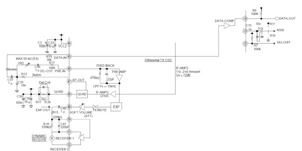
Sometimes you find a chip that does so much more than its original intended function
that it is hard to keep from using it. This is how I felt about the Toshiba TB31262F
wireless telephone chip. The '262 is a complete RF section for a full duplex analog
FM transceiver that also has data communications capability. It is intended to
operate in the US 902 MHz to 928 MHz license-free band but with a minor change in
external components it can also operate in the European 868 MHz band.
Note that even though the datasheet is all English, the pdf file contains codes for
Japanese characters and Acrobat Reader will complain. Go ahead and load the Japanese
character set when Acrobat complains.
Transmitter
Lets take a look at the transmit side of the '262.
The transmitter uses a phase locked loop frequency synthesizer. Frequency modulation
of a PLL can be performed either by summing the modulation voltage with the VCO control
voltage, or by varying the reference frequency for the PLL. Which of these techniques
is used has a direct impact on the choice of the loop bandwidth of the PLL. The '262
uses the first method of modulation since it must simultaneously transmit and receive,
and having the referee frequency modulated would make receiving using the same reference
impossible.
This means that the loop bandwidth of the PLL must be lower than the lowest desired
modulation frequency. Modulation with frequencies lower than the loop bandwidth will be
cancelled out by the feedback action of the PLL. This is the reason for the relatively
large values of the components the make up the transmit loop filter, C11 (1uF), R6 (1K), and C12 (2.2uF).
The voltage controlled oscillator for the transmitter operates at half the desired
output frequency and is completely integrated except for two inductors. These inductors
have a suggested value of 2.2 nH but for operation at lower frequencies such as the European
868 MHz band you may need to use 2.7 nH.
The '262 includes two stages of amplification for the audio signal prior to its application
to the VCO modulation varactors. The first stage is a straightforward op-amp that is AC
coupled on its input. The output of this stage is available to the designer, but it is also
internally connected to a audio level compressor.
The compressor on the transmit side works in conjunction with a matched expander on the
receive side to increase the apparent dynamic range of the FM communications channel. A
compressor and expander together is called a compandor. More information on the theory
and operation of compandors can be found in Philips Application Notes
AN174
and AN176.
[Editor's Note: Phillips Semiconductor became NXP in 2006.]
If compression of the audio signal isn't desired, the output of the first amplifier can
be connected to the second amplifier without going through the compressor. On the
schematic this would involve connecting C8 to pin 8 instead of pin 7.
If you want to send data using the '262 you simply sum in the data signal with an additional
resistor to pin 6. The value of this resistor must be sized so that the digital signals
voltage modulates the signal an appropriate amount. You should also keep in mind that
the op-amp between pins 4 and 5 will invert the data signal so that a data high level will
cause a shift to the low frequency and a data low level will cause a shift to the high frequency.
The format of the digital data that you use to modulate the transmitter with will have an
impact on how well the system works. Since the system is AC coupled, you should give
serious consideration to using Manchester encoding. For more information on Manchester encoding,
see: Wikipedia's definition.
We have used low bit rates of about 2400 bps, though the '262 should be capable of much higher rates.
The modulated PLL signal passes through a frequency doubler stage and then a power amplifier stage.
The power amplifier has a differential output which must use external components to perform the
function of a balun (balanced-to-unbalanced). This RF output must then be fed through a bandpass
filter. We at Pegasus have found that a SAW filter works best for this. In a cordless telephone
application a SAW duplexer is often used.
A duplexer is a pair of filters and a RF combiner. It has two inputs and one output. The inputs
are responsive to frequencies at opposite ends of the 902 - 928 MHz band. So you might have
the transmit side operate at 903 MHz and the receive side operate at 927 MHz.
Receiver RF Section:
The receiver in the '262 is amazingly sensitive. We have had good luck with it at signal
levels of less than -90 dBm! The input signal is amplified by a low noise amplifier stage
and then fed to a double balanced mixer. The local oscillator for the mixer is supplied
by a phase locked loop that operates off of the same reference frequency as the transmitter
PLL. The receiver PLL does not need to be modulated so its loop bandwidth can be higher
so that the phase noise can be reduced. Notice the smaller values of the loop components,
C28 and C27.
The output of the mixer is a 10.7 MHz intermediate frequency (IF) signal. This signal is
routed through standard ceramic filters like the Toko SK107 series
or the Murata SFECS10M7 series or SFECV10M7 series,
and is amplified by three stages of IF amplifiers. The amplified IF signal is then routed
to the demodulator.
Receiver Baseband:
The IF signal is demodulated using a quadrature demodulator stage. The quadrature coil
can be a standard IF can with a tuning slug or a ceramic demodulator. We have had good
performance using the Murata CDSCB10M7 series of ceramic demodulators. The advantage to using
these is that no turning is needed.
The demodulated audio signal is available on pin 47. Filtering of this signal is
performed by R13 and C35 before it is amplified and expanded. The output of the
expander goes through a volume control stage whose gain can be set digitally. This
signal can them be further amplified by the speaker driver amplifier.
The audio signal also can be routed into pin 45 to perform data slicing. This gives
a digital output signal on pin 24 that can be routed into your microcontroller for
further processing.
Getting Started with the TB31262F
I have found that this chip is popular in 900 MHz cordless telephones. When I first
started using it, I bought a Radio Shack® catalog number 43-3534 cordless telephone
for less than $20. I used its FCC identifier on the
FCC equipment authorization database
to find its certification data and was able to download the phone's schematic.
I could then remove the microcontroller that is in the phone and connect my own. This
made a very inexpensive development evaluation board for the TB31262F!
by Jim Pearce, President, Pegasus
Technologies, Inc.
Editor's note: This is a slightly updated version of an article published in SSS Online's
August 2002 edition.
The need to send relatively small amounts of data over distances less than 1km
seems to be pervasive. Electric meter reading, remote control, and alarm systems
are just a few of the myriad of uses for data links that operate in the unlicensed
frequencies.
These short range transmitters are becoming common and are often paired with receivers
to make bi-directional communications systems. For many years, several integrated
circuit manufacturers have made devices that eased the RF designer's workload in
producing a data transceiver.
The first generation of devices, which came out in the late 80s - mid 90s, consisted
of little more than an amplifier stage and a mixer. All RF filters, oscillators, and
synthesizers had to be provided external to the chip. These chips were usually only
transmitters or receivers since the level of integration was too low to incorporate
a transceiver into a single chip.
The second generation of chips, from approximately 1995 - 2000, saw the introduction
of the first transceiver ICs. These usually had internal frequency synthesizers and
mixers, but often needed several special and expensive external components such as
intermediate frequency (IF) filters. Some even needed external varactor diodes for
the on-chip voltage controlled oscillator.
We are well into the 3rd generation of single chip RF transceivers. These products
are characterized by their integration of many components that used to be added
externally. IF filters have been eliminated in some cases by the use of "Zero
IF" architectures. This means that the chip converts the received signal
directly to a very low frequency, usually less than 1 MHz. At these low frequencies,
the filtering can be provided by conventional active filters that are integrated on the chip.
In this article, I will compare and make some comments on some of the recently introduced
transceiver chips. The chips that qualified for this review are all capable of operation
in the 868MHz European band and the 915MHz US band. They all use or are capable of using
Frequency Shift Keying (FSK) for their modulation, and they all had publicly available data
sheets posted on their manufacturer's web sites. I have used some, but not all, of these
chips personally in my design work with Pegasus Technologies, but
this is principally a data sheet review. Whether the chips can actually do what their data
sheets say they can do is always in question.
All of these chips are intended to be paired with some form of microcontroller which
serves as the interface to the outside digital environment.
Chipcon
Chipcon is a Norwegian company (recently purchased
by Texas Instruments; you can read about the acquisition at
the Chipcon/TI website) that has been
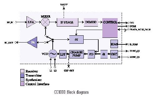
producing RF ICs for many years. Their CC1000 is a complete transceiver IC that operates
from 300 MHz to 1000 MHz. The capabilities listed in its datasheet are quite impressive.
The CC1000's frequency synthesizer, which is used for both transmit and receive modes, is
fully integrated with the small exception of a single inductor for the VCO tank. The
synthesizer covers the entire 700 MHz range of the chip in tiny 250 Hz steps.
Both the receiver and the transmitter have some very nice features:
The receiver can be programmed to use an on-chip IF filter at 150 KHz or an off-chip
10.7 MHz IF filter. Different target system requirements will point the way to which method
the designer should choose. The receiver generates a synchronized data clock from the
demodulated RF signal which greatly simplifies the firmware of the microcontroller.
The transmitter has a ramped frequency form of FSK. This method of generating
frequency shift keying relies on the synthesizer's capability of producing very small
and repeatable frequency steps. Instead of shifting, say, 60 KHz when the digital
input line shifts from a 0 to a 1, the transmitter portion of the CC1000 generates
multiple successive frequencies that sneak up on the final frequency. This greatly
reduces the bandwidth of the RF signal and makes more efficient use of the power
that is radiated.
The receive sensitivity of the CC1000 is a respectable -104 dBm for a 10-3 bit
error rate at 4.8 Kbps in the 868 MHz band. The sensitivity in the US 915 MHz band
is not listed, but is likely to be just a few dB worse than the 868 MHz spec.
The transmit power is digitally settable with a minimum of -20 dBm and a maximum
of +5 dBm in the 868 MHz band. Again, no 915 MHz spec is listed.
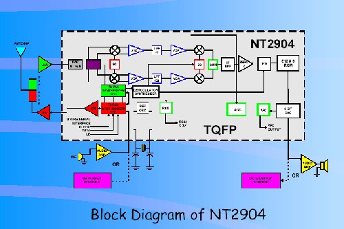
Numa NT2904
This chip is a horse of a different color! It is the only chip in this survey that
is capable of full duplex operation, i.e. it can transmit and receive simultaneously.
This is clearly targeted for use in cordless telephones. As such, the chip has
several features for FM analog operation rather than digital FSK operation.
The chip is manufactured by Numa Technologies,
a company with its headquarters in Florida that manufactures large scale ICs utilizing
BiCMOS Technology, specializing in wireless communications devices.
The Numa NT2904, which is billed as "the World's first full duplex zero-IF FM/FSK RF
transceiver IC," employs a true Zero IF receive architecture with a receive
local oscillator that operates at twice the receive frequency. This drives a
quadrature down converter which eliminates the image frequency.
The typical receive sensitivity is -94 dBm for a 10-3 bit error rate at 56.7 Kbps
and the maximum output power is 3 dBm.
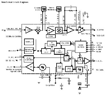
TI TRF6901
People who are familiar with the TRF6900A from Texas
Instruments might think that the TRF6901 is an incremental improvement.
In fact, it seems to be a "clean sheet of paper" design. The direct
digital synthesizer of the '6900 is gone, replaced by a simple
integer-N PLL frequency synthesizer. The two external varactors that were required
for the '6900 are gone. The VCO is completely integrated which is a welcome change.
Unfortunately, they took out digital control of the frequency shift. The shift
is now implemented by changing the load capacitance across the reference crystal
on the fly. The result of this is that a transceiver using this chip cannot have
a programmable deviation; it is set by the size of the capacitor.
Like the '6900 the '6901 uses a conventional 10.7 MHz IF and requires a ceramic IF
filter. The discriminator circuit seems to be an improvement over the one in the
'6900 and uses a standard ceramic discriminator part.
The receiver sensitivity is speced at -103 dBm for 19.2 Kbps for 860 MHz to 930 MHz.
The transmit power at the highest of its 3 power levels (well, 4 if you count zero
power) is 9 dBm.
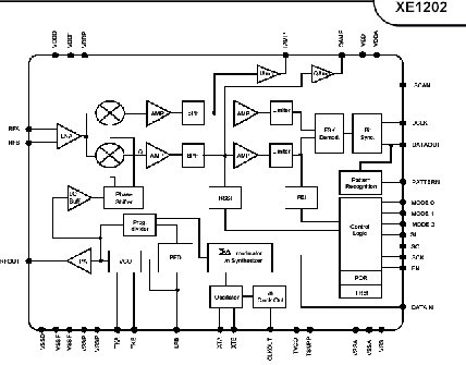
Xemics XE1202
Xemics is a Swiss fabless semiconductor company
that has made huge progress in its RF line of chips. The XE1202 has so many innovations
that it makes RF design with it almost easy! Editor's Note 4/26/06: Semtech
acquired Xemics in June 2005.
The frequency synthesizer for this chip uses one of the latest PLL architectures, the
sigma-delta fractional N synthesizer. This allows good phase noise with small frequency
step sizes. The XE1202 has 500 Hz frequency steps in the three frequency bands that it
operates in: 433 MHz to 435 MHz, 868 MHz to 870 MHz, and 902 MHz to 928 MHz.
Like the Numa chip, the XE1202 receiver uses a Zero-IF architecture. Unlike the Numa
chip, however, it uses a local oscillator that runs at the receive frequency and generates
its quadrature signals using phase shift networks.
The XE1202 receiver has a range of features such as clock recovery and pattern matching
that make the part very friendly to the microcontroller. Its typical sensitivity is
listed as -113 dBm a 10-2 bit error rate at 4.8 Kbps. This is a very sensitive receiver
but notice that this spec is for a higher error rate than other manufacturers use to spec
their parts.
The receiver provides a digital frequency error value that lets the microcontroller implement
an automatic frequency control using no extra components. This is useful for squeezing the
last dB out of the receiver when the frequency has drifted due to temperature effects.
Although less programmable than the Chipcon part, the transmitter in the XE1202 implements
a ramped form of frequency shift keying which should have about the same net improvement
in spectral efficiency. The XE1202 transmitter has 4 programmable power levels. The
typical spec for the highest power level is +15 dBm, the highest of all chips in this review.
Final Words
My nod goes to the Xemics XE1202 as the winner in this comparison. It has the highest output power
in transmit mode and the highest receive sensitivity. The XE1202 is clearly the technical standout
in this group of chips. For this reason, we chose it for use in Pegasus Technologies' new
PTSS2003 915 MHz Transceiver, a versatile FCC-approved RF module
that is just going into production as of February 2003.
The other products in this review are certainly worth consideration for projects where the mix of technical
requirements and bill-of-material cost might point in their direction.
As the market grows for wireless devices of all kinds, the IC manufacturer's will continue
to develop and expand their RF chip lineups to add more capabilities, provide lower power
options, greater flexibility, and a host of specialized ICs for different purposes.
Stay tuned -- it should be a fun ride!