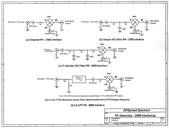
Four Different "Simple" DBM - PN Generator Interface Schemes
Hints & Kinks:
Limit maximum peak current into DBM IF pin to less than 20 Milliamperes! Use
additional input current limiting resistance, if necessary!
The simplest circuits have very poor suppression of the Sin(x) / (x) sidelobes
inherent in BPSK modulation.
Circuit (d) is capable of more than 30 dB sidelobe suppression! We use it a
lot to meet FCC / ETSI out of band requirements!
Questions, comments or suggestions on anything covered in this page are
welcome. Please feel free to share any info or special knowledge you may have.
Just drop us an email: