Reprinted from the March 2001 issue of Spread Spectrum Scene Online.
Prototyping with Surface Mount Components
-- By Jim Pearce, Pegasus Technologies
Many engineers express dismay at having to build a breadboard using components that are
only available in surface mount (SM) packages. Others will go to great lengths to
acquire parts in through-hole versions for their prototypes and then use the SM
versions for the production board.
By necessity, I have become very proficient at building prototypes using SM discrete
components and integrated circuits. There is one possible disadvantage that I should
point out up front: your first prototype must be an actual printed circuit board.
I don't find this to be a major problem since I used to go directly from schematic
to printed circuit boards even back in the through-hole days.
I find that there are many advantages to doing the initial boards using SM components:
The prototype board is the same physical size as the ultimate product. Since
the board itself must be considered a component for many RF
boards, this is absolutely necessary.
The surface mount components are physically smaller than their through-hole
equivalents, so they are less affected by parasitic effects.
It is easier to change out resistors and capacitors to try different values.
You don't have to get solder out of a plated-through hole. Simply bring the hot
air soldering hand piece up to the part that you want to remove, grasp the part
with tweezers, and lift it off.
You can try different values of discrete components rapidly without solder
at all. Just lay the part across the pads and apply a small pressure with your
tweezers in the middle of the part so you don't contact either end of the part.
Observe the 'scope, meter, or whatever instrument you're using for the change
in circuit behavior, and go on to the next value.
The board lasts through more component changes than a through-hole board.
I have had through-hole pads lift and break after just one unsoldering operation.
This rarely happens with a SM board, though pads with no connections to help
dissipate heat will occasionally lift off the board with little provocation!
While a megabuck SM repair station is not necessary (I have gotten along just
fine without one), there are a few bench tools that are essential for SM prototyping.
They are listed below, roughly in order of importance.
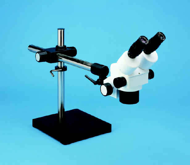
Stereo Microscope. Anyone who is doing serious SM work must have
a good stereo microscope for soldering, desoldering, inspection, or probing
operations. When selecting a microscope, be sure to pay particular attention
to the working distance -- the clearance between the microscope objective lens
and the item that it is focused on. I once worked with an otherwise fabulous
microscope that had only two inches of working distance. Boy, was it ever
easy to burn the plastic ring light on that microscope with a soldering iron!
A negative power lens will increase working distance more than it will
decrease the magnification.
Scienscope supplies reasonably priced
stereo microscopes.
Good tweezers. Tweezers are next on my list since they are the tool
that you will handle most. I prefer foam cushioned stainless steel tweezers
with curved tips like the
Erem E7SA. A good pair of tweezers will make your life much easier!
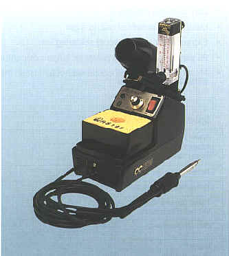
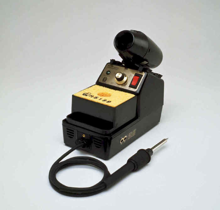
Hot air soldering iron. A hot air soldering iron is useful both for
initial soldering and for desoldering. My choice of hot air tools is the
Edsyn 971HA. It is one of the less expensive
units but is still quite capable. In fact, it has some features (possibly unintended)
that make it easier to use than most hot air soldering tools. The most important
of these is that the air tubing from the base to the handpiece is flexible and
runs at a position where you can squeeze off the air flow with your index finger
while moving the iron near to the component that you wish to work on. This
prevents blowing off dozens of components while getting everything arranged
under the microscope! This soldering station is intended for operation with
compressed air and it comes with air handling hookups. I don't have shop air,
but rather than pay hundreds of dollars more for a unit with a built in pump I
went to WalMart and bought the largest aquarium air pump they had in stock. With
very simple and reversible modifications, the soldering iron works quite nicely
with this air source.
I recommend Howard Electronics as a source
for microscopes and soldering supplies.
Stainless steel shim pin lifter. The quickest and least damage-prone
method of unsoldering large surface mount integrated circuits is to use a stainless
steel shim in an exacto-knife handle. Carefully slide the shim under the pins of
the IC while heating with the hot air soldering iron, and they pop right off.
I have desoldered many .5mm pitch QFP parts using this technique, and have been
able to reuse the parts and have not damaged any of the pads on the board. This
method is also quite rapid. A 48 pin part might be removed in as little as 30
seconds. And it doesn't require expensive, complicated special purpose hot air
nozzles. This technique is championed by Edsyn, who include a roll of stainless
shim stock with their soldering irons. I've not seen this method described anywhere else.
Fine tipped soldering iron. I use a contact (traditional) soldering
iron for most initial board building. A well-tinned very narrow tip is a must.
Any manufacturer's iron will do but the smaller and lighter hand pieces are very
nice for big jobs.
You might try the Edsyn 951SX:
Flux pin. After swapping many components to find the correct values,
it's inevitable that the solder on the board will become grainy and laced with
impurities. I like to use a
Kester low-solids flux pin to clean the board
up and make better solder joints. With one of these pins you simply touch the
contaminated solder and gently reheat the area with the hot air soldering iron
(being careful not to blow parts away), and the solder gets bright and shiny as
if by magic. Better still, with a low-solids pin, you don't even have to wash
the flux off afterwards.
Several years ago, many of the no-clean fluxes were useful only for digital circuits
since they had relatively high conductivity and would interfere with the operation
of any high impedence analog circuits. With the new low-solids, no-clean fluxes
that are out now, I have not run across this problem.
In conclusion, I have found that the proper tools make prototyping with surface
mount components easier and faster than any of the traditional prototype methods.
Certainly it is no longer an onerous task to be avoided at any cost!