Few subjects in RF design elicit as many blank looks as Eb/N0.
Read the article and associated links below to find out more about this important subject!
What's All This Eb/No Stuff,
Anyway? By Jim Pearce (With Apologies to Bob Pease)
(This article originally appeared in the Fall 2000 issue of Spread Spectrum Scene Online.)
Anyone who has spent more than ten minutes researching digital communications has run across
the cryptic notation Eb/No.
Usually this shows up when discussing bit error rates or modulation
methods. You may have a vague feeling that it represents something important about a digital
communication system, but can't really put a finger on what or why. So let's take a look at just
what this Eb/No thing is and
why it's important.
First of all, how do you pronounce Eb/No?
Most engineers that I know say "E bee over en zero," though some of the more fastidious
ones say "E sub bee over en sub zero". At any rate, even though "No" is
usually written with an "Oh" instead of a zero, it is not pronounced as the
word "no".
Eb/No is classically defined as
the ratio of Energy per Bit (Eb) to the Spectral Noise Density (No). If this definition leaves
you with a empty, glassy-eyed feeling, you're not alone. The definition does not give you any
insight into how to measure Eb/No
or what it's used for.
Eb/No is the measure of signal
to noise ratio for a digital communication system. It is measured
at the input to the receiver and is used as the basic measure of how strong the signal is.
Different forms of modulation -- BPSK, QPSK, QAM, etc. -- have different curves of theoretical bit
error rates versus Eb/No as shown
in Figure 1. These curves show the communications engineer
the best performance that can be achieved across a digital link with a given amount of RF power.
Figure 1. BER vs Eb/No (Thanks, Intersil for this figure)
In this respect, it is the fundamental prediction tool for determining a digital link's
performance. Another, more easily measured predictor of performance is the carrier-to-noise
or C/N ratio.
So let's pretend that we are designing a digital link, and see how to use Eb/No and C/N to
find out how much transmitter power we will need. Our example will use differential quadrature
phase shift keying (DQPSK) and transmit 2 Mbps with a carrier frequency of 2450 MHz. It will
have a 30 dB fade margin and operate within a reasonable bit error rate (BER) at an outdoor distance
of 100 meters. Hold on to your hat here! Remember that when we play with dB or any log-type
operation, multiplication is replaced by adding the dBs, and division is replaced by subtracting
the dBs.
Our strategy for determining the transmit power is to:
Determine Eb/No for our desired BER;
Convert Eb/No to C/N at the receiver using the bit rate; and
Add the path loss and fading margins.
We first decide what is the maximum BER that we can tolerate. For our example, we
choose 10-6 figuring that we can retransmit the few packets that will have errors at
this BER.
Looking at Figure 1, we find that for DQPSK modulation, a BER of 10-6 requires
an Eb/No of 11.1 dB.
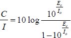
OK, great. Now we convert Eb/No
to the carrier to noise ratio (C/N) using the equation:
Where:
fb is the bit rate, and Bw is the receiver noise bandwidth. [EDITOR'S NOTE: See Phil Karn's comment below concerning
this equation.]
So for our example, C/N = 11.1 dB + 10log(2x10⁶ / 1x10⁶) = 11.1 dB + 3dB = 14.1dB.
Since we now have the carrier-to-noise ratio, we can determine the necessary received carrier
power after we calculate the receiver noise power.
Noise power is computed using Boltzmann's equation:
N = kTB
Where:
k is Boltzmann's constant = 1.380650x10⁻²³ J/K;
T is the effective temperature in Kelvin, and
B is the receiver bandwidth.
Our receiver has some inherent noise in the amplification and processing of the signal.
This is referred to as the receiver noise figure. For this example, our receiver has a 7 dB
noise figure, so the receiver noise level will be:
N = -107 dBm.
We can now find the carrier power as C = C/N * N, or in dB C = C/N + N.
C = 14.1 dB + -107dBm = -92.9 dBm
This is how much power the receiver must have at its input. To determine the transmitter
power, we must account for the path loss and any fading margin that we are building in to the
system.
The path loss in dB for an open air site is:
PL = 22 dB + 20log(d/λ)
Where:
PL is the path loss in dB;
d is the distance between the transmitter and receiver; and
λ is the wavelength of the RF carrier (= c/frequency)
This assumes antennas with no gain are being used. For our example,
PL = 22 dB + 20log(100/.122) = 22 + 20*2.91 = 22 + 58.27 = 80.27 dB
Finally, adding our 30 dB fading margin will give the required transmitter power:
P = -92.9 + 80.27 + 30 = 17.37 dBm = 55 mW
Our result, 55 mW, is well within a reasonable power level for spread spectrum links in the
2.4 GHz band. So we see that, in this example, our 100 meter range is a very reasonable
expectation.
So, what is all this Eb/No stuff?
Simply put, it's one of the "secrets" used by top RF
design engineers to evaluate options for digital RF links, and is a crucial step in the design of
systems that will meet performance expectations.
Comments from Phil Karn
From: Phil Karn
To: Jim Pearce
Sent: Monday, April 23, 2007 3:47 AM
Subject: Eb/No Explained
[Editor's Note: Phil is a Qualcomm engineer who is very well known in the radio community.
His website is at www.ka9q.net, and has a number of articles of interest to
electronics/wireless aficionados/practitioners.]
Hi Jim,
I found your article "What's All This Eb/No Stuff, Anyway?" while
looking for references that would help me better explain this stuff.
It's a good paper, but I have a tiny little nit. Your first equation says:
C/N = Eb/No * fb/Bw, where
fb is the bit rate, and
Bw is the receiver noise bandwidth
Usually I see this stated as
C/N = Eb/No * (R/B), where
R = bit rate
B = channel bandwidth
I.e., "channel bandwidth" instead of "receiver noise bandwidth".
I see two problems with using receiver noise bandwidth in this equation.
First, Eb/No is supposed to be a universal figure of merit for any kind
of receiver, so it's measured at the receiver input terminals and is
independent of anything inside that receiver. Different receiver designs
for the same signal might use multiple filters with different shapes and
bandwidths, but that would not affect the Eb/No of the signal at their
inputs.
The other problem is that there's more than one definition of bandwidth.
Noise bandwidth is just one of many. In fact, that's precisely why Eb/No
is such a useful figure in the first place: it completely avoids
arguments over the exact system bandwidth and/or which definition of
bandwidth to use to measure it. No is the noise power spectral density
in units of watts/Hz (or milliwatts/Hz), so the only filter bandwidth
that's relevant is that of the spectrum analyzer being used to measure it.
The procedure I like for measuring Eb/No on the bench is to use an
analyzer to measure the signal power with a resolution bandwidth wide
enough to capture all of the signal. Then I turn off the signal source,
turn on the noise generator, and measure the noise power on the analyzer
with the resolution bandwidth set to the user data rate. (Naturally I
have to ensure that both signal and noise swamp the analyzer's own noise).
Then I calculate Eb/No by simply subtracting the noise power measurement
from the signal power measurement. Setting the analyzer RBW to the user
data rate simplifies the calculation by causing the data rate and noise
bandwidth terms to cancel and fall out of the equation.
I found your article while trying to explain to another person that
his Eb/No measurement methods are wrong. This fellow claims to have invented a
family of "ultra narrow band" modulation methods that are in fact ultra
wide band (UWB) plus a very strong carrier that wastes most of the
signal power. Among many other mistakes, he has fallen into the trap of
confusing noise bandwidth with other, more relevant definitions of
bandwidth, and his receivers have filters with noise bandwidths that are
much smaller than the Nyquist rate. This is how he has fooled himself
into thinking that his signals are narrow band.
Anyway, thanks again for the article you published way back in 2000.
Regards, Phil
Discussion Between Phil Karn and Steve Liang about Eb/No, July 2009
Printed here with permission from both Phil and Steve, and a real nuts and bolts discussion!
From: Steve Liang, Wednesday, July 22, 8:18 a.m.
Jim or Phil, Does either of you know where can I find BER vs. Eb/No waterfall plots, Excel spreadsheet even better, for different
modulation schemes (BPSK, QPSK, 8PSK, and 16QAM)?
Phil - Does Qualcomm have BER vs. Eb/No data for different modulation schemes and for different Viterbi Turbo Coder rates?
Thanks,
Steve Liang
Sprint Nextel, San Francisco RFE
*******
From: Steve Liang, Wednesday, July 22, 2009 2:48 p.m.
Jim and Phil- I wasn't thinking clearly this morning. Don't worry about the 2nd question I have for Phil, it's not a valid question for
Eb/No (1/2 rate or 1/3 rate FEC encode has not effect on BER.) Still like to have BER vs. Eb/No data though.
Thanks,
Steve Liang
*******
From: Phil Karn, Wednesday, July 22, 3:13 p.m.
BER vs Eb/No plots for the standard modulation techniques are in all the comm theory textbooks. The
Wikipedia article for
BPSK has plots, with derivations, of the bit error rate vs Eb/No for uncoded BSPK, QPSK, 8PSK and 16PSK.
FEC most definitely does affect the BER vs Eb/N0 plots. I can't speak to our own decoders off the top of my head,
but plots for the common FEC schemes are also in the textbooks, certainly for the common Viterbi decoded codes.
Note that "The Viterbi Algorithm" is an algorithm for decoding convolutional codes. There's no such thing as a "viterbi code."
A Turbo code is a different kind of code made typically of two small convolutional encoders plus an interleaver. It is
decoded by one of several methods, some including modified versions of the Viterbi algorithm that can produce "soft"
decisions, i.e., estimates of the reliability of each output bit rather than just the algorithm's best guess as to its most
likely value. This is important in decoding turbo codes since the process is iterative, feeding the results of one decoder
into another until the data stops getting better.
*******
From: Steve Liang, Wednesday, July 22, 2009 7:50 p.m.
Phil, Thank you for the fast response. So, you do think FEC would reduce Eb/No requirement for a specific BER? I thought your
comment to Jim's "Eb/No Explained" was "Eb/No is supposed to be a universal figure of merit for any kind of receiver,
so it's measured at the receiver input terminals and is independent of anything inside that receiver"?
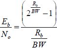
My EVDO infrastructure provides mobile's Ec/Io measurements. I am trying to correlate the Ec/Io measurement to expected EVDO data throughput through:
Rb = User data rate W = CDMA carrier bandwith
And I can get
from
And user data rate will be:
The only missing part for the above equation now is the Eb/N0. I think the Eb/N0 is a set point controlled by
EVDO infrastructure vendor, it's not going to be easy to get it without run a deep debug trace at the system.
An alternative way to get user data throughput would be from the Qualcomm MSM chip, which I think is sending a 'DRC Index' up to CSM at network that maps to
Payload size, Modulation scheme, FEC code rate, number of slots the payload will be transmitting, etc. Do you know where can I find the C/I to 'DRC Index' mapping table?
*******
From: Phil Karn, Monday, July 27, 2009 8:27 p.m.
You asked if I think FEC would reduce the Eb/No requirement for a specific BER.
Yes, that's precisely the purpose of using FEC. It allows you to reduce the required Eb/No closer to the theoretical limit,
which is -1.6 dB for infinite bandwidth. For limited bandwidth, the required Eb/No is higher; e.g. at a ratio of 1 bit/sec
per hertz of bandwidth, the absolute minimum Eb/No is 0 dB.
You said, "I thought your comment to Jim's Eb/No Explained was 'Eb/No is supposed to be a universal figure of
merit for any kind of receiver, so it's measured at the receiver input terminals and is independent of anything inside that receiver?"
That's right, the Eb/No of a particular signal is set at the input terminals of a receiver. The Eb/No at that point cannot be
affected by anything inside that receiver. Note that this is distinct from the minimum *required* Eb/No needed to make that receiver actually work.
The Ec/I0 ratio is actually the Ec/(I0+N0) ratio; the interference and thermal noise are summed, but in practice the interference is much
stronger so the noise can usually be disregarded. In any event, in a CDMA system interference looks like noise so they can be considered the same thing.
The CDMA reverse link uses a closed-loop power control scheme to try to set the Eb/N0 at the base receiver to a specific value that
enables the receiver to just work well. There's no point in making the signal any stronger, as that would just increase the interference
to other users. The cell receiver measures the Eb/N0 and tells the mobile transmitter to go up or down in 1 dB steps.
The CDMA forward link also uses closed loop power control, but it is much less critical to the operation of the system and to be
honest I don't know as much about it. It's less critical because, unlike the CDMA reverse link, the CDMA forward link isn't a
multiple access link. Interference exists from other cell site transmitters, but it's not as significant as the interference
from other mobile transmitters on the reverse link because the cell site is trying to demodulate all those mobile transmitters
at once. The mobile is not trying to demodulate multiple cell site transmitters at once except when it's in soft handoff, and
in that case it's okay for one cell to be much stronger than the other because they're both sending the same information.
*******
From: Steve Liang, sent Tuesday, July 28, 2009 2:34 p.m.
Phil -- Thank you for the detailed explanation. The theoretical Eb/No for infinite bandwidth and the Eb/No for
1 bit/sec per hertz of bandwidth are new to me. Would you mind letting me know how you get those numbers?
I failed to get those numbers trying to use the following relations:
Shannon's Channel Capacity Theorem:
And
Gives
I am not getting your numbers when I take limit for BW → infinity?
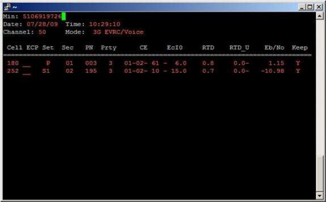
While we are on this topic, can you help me with this mystery I always have with Lucent call trace output. It gave unrealistic Eb/No values (see example below):
Last question, sorry for so many them – Does Qualcomm have a published table/chart for Eb/No vs. modulation scheme + different code rate for a specific BER, FER, or PER?
*******
From: Phil Karn, Tuesday, July 28, 2009 1:13 PM
You wrote: "The theoretical Eb/No for infinite bandwidth and the Eb/No for 1 bit/sec per hertz of bandwidth are new to me.
Would you mind letting me know how do you get those numbers?"
That's just the Shannon limit!
C = B * log2(1+S/N)
C is the channel capacity in bits/sec, B is the channel bandwidth (you can't send *anything* outside it), S is the received
signal power, and N is the received noise level, again both being confined to bandwidth B.
You can rework Shannon's basic equation as follows:
C = B * log2(1+(Eb/N0) * (C/B))
This substitution works because S, the signal power, is just the energy per bit times the bit rate C, and N, the noise power,
is the bandwidth times the noise power spectral density N0. Now we see the explicit relationship between channel capacity and R/B,
the modulation efficiency in bits/sec / hz. You can rearrange this to Eb/No >= (S/N) / (C/B) = (2^(C/B) - 1) / (C/B)
In other words, this is the absolute minimum Eb/No ratio required for a link with a given C/B (bits/sec/Hz) ratio. This is only
a theoretical minimum; any real system will do worse, though with modern FEC (turbo coding) you can now often get within a dB of
the Shannon limit.
If you plug in C/B = 1 bit/sec/Hz, then you get a Eb/No = 1, which is 0 dB. If we decrease C/B, i.e., use excess bandwidth, the
required Eb/No decreases but not forever. If you take the mathematical limit as C/B approaches zero you get an answer of ln(2)
or 0.693 or -1.6 dB. This is the famous "Shannon bound" that says no communication system, even if it has infinite bandwidth,
can operate below an Eb/No of -1.6 dB.
That's where those figures came from.
Look closely at that exponential. As you increase C/B, the bits/sec/Hz, the minimum required Eb/No to make the link work *even
in theory* increases *exponentially*. Yes, it's diminished somewhat by the (C/B) term in the denominator, but that doesn't
grow nearly as fast as the exponential in the numerator. The C/B factor accounts for the fact that when you transmit a group
of bits as a single symbol, that symbol can use the combined energies of all those bits.
Anyway, this is why you don't see systems running hundreds or even tens of bits/sec per hertz of bandwidth. The densest one I
know of in widespread use is 256QAM in digital cable modems and TV. That's 256 possible values per symbol, or 8 bits/symbol,
or 8 bits/sec / Hz. This is possible only on a hybrid fiber/coax cable network with few amplifiers and low distortion.
The equation you have with Ro in the result is for something called the "R0", or the computational cutoff rate, a value below
the Shannon capacity C. The discovery of Turbo codes made this formula obsolete.
R0 was once thought to be the practical limit for any real FEC running on hardware we could actually build, and it would be
impractical to exceed it. This was true for sequential decoding, one of the earliest of the powerful FEC decoding techniques,
but sequential decoding was displaced by Viterbi decoding, which has since given way to Turbo decoding although it still uses
a modified form of the Viterbi algorithm.
You also asked if Qualcomm has a published table/chart for Eb/No vs. modulation scheme+ different code rate for a specific BER, FER,
or PER. I'm not sure, but this might be in the various EIA/TIA standards for our stuff. In particular, the 1xEV-DO spec might have
specs for the required Eb/No for each of the many modulation modes and data rates.
I can't really comment on the channel analyzer picture since I don't know anything about your analyzer. If I had to guess I'd say
those two Eb/No figures were for the two channels participating in a CDMA soft handoff. In this case, the receiver combines their
energies before decoding. In this way it can often get enough energy to decode a bit that would not be possible with just the data
from one cell site receiver. To add the two Eb/No ratios you have to first convert them back to linear:
1.15 dB -> 1.303
-10.98 dB -> 0.08
1.303 + 0.08 = 1.383 -> 1.41 dB. Not much better, but still better than just the one channel. What did the voice sound like?
It might actually work at this low level, though it wouldn't sound great.
Hope this helps.
[Editor's note 7/9/14: Changed "infinity" to "zero" in the paragraph above that begins "If you take the mathematical limit as C/B approaches zero ..." per
correction from Phil Karn 6/28/14.]
*******
From: Steve Liang, sent Tuesday, July 28, 2009 4:24 p.m.
Phil, thank you so much, this really answered the mystery I had about Eb/No.
While I was taking my after lunch I did notice I made a mistake in Shannon's:
Should be (1+S/N): so if we can have infinite signal power or bandwidth we can achieve infinite data rate.
Also the S/N and Eb/No are log values; I should convert them to decimal for the calculation.
Good to talk to you, I have learned a lot.