This is the second page of our site devoted to those nifty little PICs. The contents
listed below can be used to navigate back and forth between this page and the previous
page easily and quickly. Just press a link to go directly to the item you're interested
in. Or, just scroll down the page to read about some interesting PIC applications.
by Jim Pearce
President, Pegasus Technologies, Inc.
I remember the first time I opened up a Swiss watch when I was a kid.
(I was always opening up things to see what made them tick!) The beauty
of the jewels, the shinning silver and gold metal, and the polished surfaces
made a life-long impression that the Swiss people really know how to do thing right.
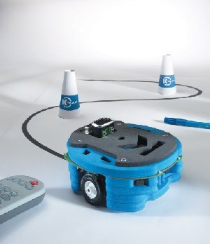
Hemisson is no exception! The Hemisson robot is a teaching tool for the principles
of robotics aimed at students aged 10 to 15, and for hobbyists of any age who are
interested in learning more about the principles of robotics and artificial intelligence.
The Hemisson is about five inches in diameter, made of blue foam, and contains a PIC16F877
microcontroller, two motors, four LEDs, six switches, eight infra-red proximity sensors, an
Infra-red remote control port, a buzzer, and an RS-232 port. It is designed to accept a
number of extension modules that expand its capabilities even further.
The built-in firmware has several preprogrammed modes of operation that will let you play
with Hemisson straight out of the box. In addition to "avoid the wall" and
"follow the line" programs which are fun, I especially liked the hypocycloid dance
mode. If you put a felt tip pen through the hole in Hemisson's middle and place him on a
piece of paper while in this mode, he will draw pretty designs. The robot can also be
operated through a standard TV remote control or via an RS232 cable connected to your computer.
I found setup to be easy and performance was good, although you do have to be careful with
sunlight and incandescent lighting, which can confuse Hemisson. Also, in the obstacle avoidance
mode, he avoided some types of obstacles better than others.
The full potential of Hemisson is achieved with the Bot-Studio and Webots-Hemisson. Bot-Studio
is a finite state machine programming language that runs on a PC and that downloads the compiled
instructions to Hemisson. This allows many rules for the motion of Hemisson to be defined and
easily executed. The firmware is open source which allows for modifications to suit your
particular applications.
My 15 year old son played with Hemisson straight out of the box and had fun with its preprogrammed
modes. He was not able to understand the FSM programming without help from me. I suspect that he
is not unusual in this regard. For a class project or other environment where an adult can guide
the children in learning robotics, the Hemisson should provide a worthwhile platform. For hobbyists
who are already familiar with some level of programming, it should be easy to learn and a great way
to expand your knowledge of robotics and AI.
The manual provided enough detail to get you started, and was relatively clearly written although
obviously not by a native speaker of English. It includes a summary description of the
microcontroller and a link to find out more information about its capabilities, and a schematic
(although it was hard to read because it was so small). The documentation on the CD Rom was
also adequate, and there is a website (http://www.hemisson.com/) that offers more information,
a newsletter, and a users forum.
A variety of modules that extend the capability of Hemisson are available now. One of these is
a radio module that permits wireless communications with your PC, and another is a tiny linear
camera that mounts on top of Hemisson and allows it to perceive its environment in a more
sophisticated manner. For hobbyists, there's an interface board to make it easier to install your
own electronics. Additional modules are under development. We didn't try out any of these modules,
but they look like they could be fun.
Hemisson is designed, manufactured and distributed by K-Team S.A.,
a Swiss company that develops, manufactures and markets not only the Hemisson, but also the Khepera
Linecard, high-quality mobile minirobots for use in advanced education and research, and KoreBot
and Kameleon, advanced miniature single board controllers for the automation industry.
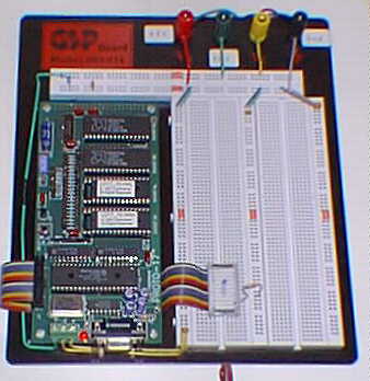
PIC17C42 Firmware PN Generator - De-Spreader (Use for TX or RX)
PIC17C42 Firmware PN Generator Design Description
To run PN-GEN.asm on Proto-17:
Assemble PN-GEN.asm to PN-GEN.HEX
type c:\rf-ss\cross16\c16 pn-gen.asm -l pn-gen.lst -h pn-gen.hex
Set jumper to 22 & 24 and starts up procomm (procomm configurations are in manual)
reset proto-17 and user should get prompt from proto-17. Type => E to erase Flash EPROM;
type => U to initiate program upload.
Choose ASCII upload in procomm and upload PN-GEN.HEX
Proto-17 should return some successful message.
Hold down reset button and set jumpers from 22 & 24 to 23 & 25 (keep reset button down).
Release reset button, and pn-gen.hex should be running now.
To check output from parallel port A, tie test probe to pin#6 of CN-1 for RA2 and pin#5 for RA3.
pullup resistors are required on these pins.
To load in another file, repeat step 1 through 7.
Memory Map
PIC17C42 has a separate program memory and data memory. All the run time variables are stored
or read from the data memory which is allocated from 0x00 to 0xff and are 8 bit wide data.
If more than 256 bytes of data memory are desired, a swap between data memory and program memory
can be done by using TABLRD and TABLWT instructions (time consuming process).
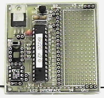
Parallel Port
Since proto-17 is running in microprocessor mode, only parallel A is available as built in
I/O port, and most of the bits of port A are input only and with very few output ports.
Since PIC17C42 doesn't have a direction register for its parallel port, a pullup resistor
is needed for output, and a 0 must not be written to the port when configured as output.
Timing problems
A low to high or high to low transistion appears to have different but consistent delays.
A single bit high has a cycle time 60ns shorter than the regular instruction time (250ns),
and a single bit low has a cycle time 60ns longer than the regular instruction time.
For multiple high bit, the cycle time will still be 60ns shorter than the expected cycle length.
E.g. 5 high bit will result in a cycle time of 5x250ns-60ns = 1190ns.
From bit to bit, several instructions needed to be executed in order to call up a new
PN sequence. The number of instructions that we can put in will depends on how much
we can tolerate between bit to bit, but the detail analyses are not yet done.
Hardware problem
Since there are only 256 bytes of data ram on the chip, if more memory is desired,
two external ram are needed to provide more program memory (RAM) for swapping. It will
be even more complicated if the 2K internal EPROM are not large enough to hold the program.
If that is the case, two external EPROM will also be needed besides the external RAM, which
implies that an address decoder will also be needed.
To see what could be done quickly, simply and cheaply with the new "Basic Stamp"
type of PIC development boards, we decided to try out VERSATECH's FBASIC TICKIT.
We first programmed it to output the fastest squarewave that it was capable of, using its 20
MHz clock.
Obviously this is no big deal -- it showed us however, that the PIC when running FBASIC
can output square waves of up to 40 or 50 kHz. So we went ahead and tried out outputting
a 31 bit, maximal length sequence shift register code (a code derived from a 5 bit long shift
register with one EXOR for feedback).
Again no big deal -- it showed us, however, that the PIC when running FBASIC can output
PN codes of up to about 40 kHz. So we went ahead and tried out outputting maximal length
sequence shift register (MLSR) codes of length 15 and Barker codes of length 13, 11 and 7.
Just download the files below to see what we did.
These little examples prove that these "BASIC STAMP" -like PIC development tools
can actually do something useful -- with very simple programming and a minimum of expense.
While 40 kHz PN codes may only be useful for low speed Packet communications or educational
demonstrations, assembly language programming can allow PICs to go up to at least the 1-2 MHz
Chip rate range.
Spread Spectrum Scene Online is managed and maintained by Pegasus Technologies. Click on
our logo below to find out more about our RF, Wireless, and advanced digital/FPGA design consulting
services. We can help you get your quality RF products to market!